

3D Models and Renderings in CAD Software: What Your Model Is Accurate Enough For
A 3D model is never accurate in general. It’s accurate for something. A model detailed enough to produce a photorealistic render can be useless for generating a Bill of ...
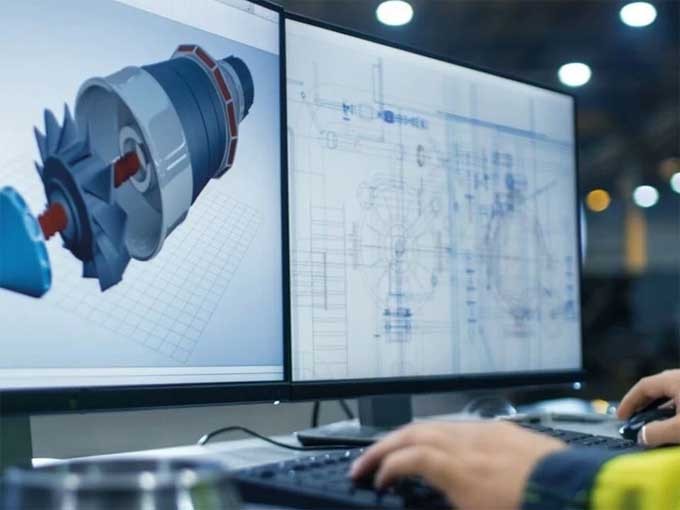
A 3D model is never accurate in general. It’s accurate for something.
A model detailed enough to produce a photorealistic render can be useless for generating a Bill of Materials. A model that drives clash detection perfectly may have surfaces too crude to show a client. The same geometry, the same file, two different verdicts – because accuracy is a question about purpose, not about quality.
This matters more in 2026 than it used to, because the number of things a 3D model is expected to do has grown. In construction, oil and gas, and manufacturing, one model is now expected to produce presentation renders, feed automated clash detection across disciplines, generate quantities that reach SAP, and serve as the environment for operator training. Each of those asks something different about it.
This article covers the rendering pipeline briefly, then spends most of its length on the part that decides project outcomes: what each downstream use requires from the model, and what breaks when the accuracy doesn’t match the job.
What accuracy means, depending on the job
| What you want the model to do | What it has to be accurate about | What breaks when it isn’t |
| Produce a client-facing render | Surfaces, materials, lighting, proportion | An approval granted on a false impression – expensive to reverse later |
| Support clash detection across disciplines | Position, routing, real component geometry | False clashes bury the real ones; real clashes surface on site |
| Generate a BoM your ERP will accept | Attributes, tags, classification, naming | Errors enter procurement – wrong materials, wrong quantities |
| Drive a takeoff or an engineering calculation | Dimensions, quantities, layer structure | The number is wrong, and nobody finds out until fabrication |
| Become a training environment | Spatial layout, instrument placement, access routes | Operators learn a plant that doesn’t match the one they’ll run |
Most of the frustration teams have with their 3D models traces to a mismatch in this table: a model built for one row being asked to do the work of another.
The rendering pipeline, briefly
Visualisation remains a legitimate use of 3D models, and the process is well served by standard CAD tools. The pipeline runs in five stages.
- Conceptualisation. Rough sketches and a clear definition of what the model is for – purpose, level of detail, target software. This is where the accuracy question above should be answered, and usually isn’t.
- Modelling. Building the geometry in the CAD platform: points, lines, surfaces, solids, then the surface detail that gives the model its character. AutoCAD dominates in architecture, SolidWorks in mechanical engineering.
- Texturing and materials. Applying wood, metal, glass, or fabric to surfaces, with bump and displacement techniques adding apparent depth without raising the polygon count.
- Lighting and environment. Simulating natural or artificial light sources – intensity, colour, direction – and placing the model in a context, from a plain studio backdrop to a full exterior scene.
- Rendering and post-processing. Converting the 3D scene to a 2D image or animation, whether through ray tracing for photorealism or real-time rendering for interactive use, then adjusting the output for colour balance and contrast.
Accurate visualisation earns its keep in three specific ways: virtual prototypes can be checked for fit, form, and function without building anything physical; design problems surface early, while they’re still cheap to fix; and stakeholders who can see what they’re approving approve faster and change their minds less often.
That’s the visualisation half. The engineering half is where the model stops being a picture and starts being a data source.
Beyond rendering: the model as engineering data
In engineering-intensive industries the 3D model serves a fundamentally different purpose. It isn’t there to be looked at – it’s there to be read by other systems.
Interdisciplinary clash detection
In large facilities, separate teams model piping, structural, electrical, and instrumentation. When those models are combined, clashes are inevitable – and detecting them was never the hard part. Managing their resolution across disciplines, teams, and model revisions is.
A custom 3D model review tool with integrated clash detection and version control cut average clash resolution from 3-5 days to under one day, reduced duplicate clashes by 90%, and shortened review cycles from about ten business days to three or four. The change wasn’t better detection – it was moving resolution tracking out of spreadsheets and into the review environment, with a named owner and a deadline on every issue.
What the model has to get right for this: position and routing accuracy, and component geometry that reflects real parts rather than placeholders. A model full of generic representative blocks will generate clashes that don’t exist and miss ones that do.
Automated data extraction
Engineering data embedded in the model – dimensions, material specifications, quantities, component attributes – can be extracted automatically into Excel, SAP, or procurement systems, eliminating the manual copy-paste that introduces errors and consumes engineering hours.
One data extraction tool reduced reporting time from hours to minutes while eliminating formatting errors entirely. Every report reflects the current drawing revision, so there’s no lag between a design change and the data reaching the people who act on it.
What the model has to get right: consistent layer structure and attribute naming. Extraction runs against your drawing standards, not against a generic data model – if three engineers tag the same component three ways, automation will faithfully propagate all three.
CAD-to-ERP integration
Bills of Materials generated from models in AutoCAD Plant 3D or AVEVA E3D can be synchronised directly with SAP S/4HANA. A custom integration for a midstream gas processing plant improved data synchronisation by 85% and reduced data-related reworks by 70%, compressing BoM data entry from 4 hours to under 15 minutes per update.
What the model has to get right: classification and tagging that can be mapped to your ERP’s material master structure. This is the least glamorous accuracy requirement and the one that most often blocks the project.
Training environments and digital twins
A 3D model doesn’t have to stop being useful after construction. Connect it to real-time sensor data, a behavioural model, and an operable interface, and it becomes a digital twin. Stop short of the live connection and you get something almost as valuable: a high-fidelity simulator.
An operator training simulator built from a facility’s detailed 3D model, P&IDs, and process flow diagrams cut operator onboarding from 4-6 months to 2-3, reduced incidents during onboarding by 80%, and lowered cost per operator by 60% – with procedure retention rising from around 60% to over 90%.
What the model has to get right: spatial layout, equipment positions, instrument locations, and access routes matching the physical facility. A simulator built on a generic plant layout forces operators to mentally re-map it onto the real one – an extra cognitive step that undermines the training it was built to deliver.
The accuracy decision happens early, and it’s usually implicit
Here’s the practical point. Teams rarely decide how accurate a model needs to be. They model whatever standard is habitual, and discover the gap two years later when someone tries to generate a BoM from it and half the components have no classification.
Modelling to the highest possible fidelity everywhere isn’t the answer either – it’s expensive, slow, and produces files that are painful to work with. The useful question at the start of a project is narrower: what will this model be asked to do after the drawings are issued? If the answer includes automated extraction, ERP integration, or an operations handover, the requirements for naming, classification, and attribute completeness need to be set before modelling starts, not retrofitted after.
Retrofitting is possible – we do it regularly – but it costs more than getting it right the first time, and it’s the single most underestimated line in any CAD automation budget.
Conclusion
3D models in CAD software serve two different masters. For visualisation, they produce images for presentations and approvals, and standard CAD tools handle that well. For engineering, they’re a data source driving clash detection, quantity extraction, ERP synchronisation, and operator training – and that pipeline requires custom development: plugins built on AutoCAD API, Revit API, Plant 3D SDK, or AVEVA PML that extract, validate, and transform model data for the systems downstream.
The question that decides which of those you get isn’t which CAD platform you run. It’s whether the model was built accurately for the job you’re about to ask of it.
Share this post:
Wondering whether your models can support the automation you want?
Tell us what you'd like to generate from them – takeoffs, BoMs into your ERP, a training environment – and which platform they live in. We'll tell you what's achievable with the models as they are, and what would need to change first. Including when the answer is that they're already fine.