Why Process Matters in Engineering Automation

Predictability

Fixed milestones tied to real deliverables, not billable hours. You know what ships and when.

Transparency

Bi-weekly demos of working software. No month-long silences followed by a surprise.

Engineering-First Discovery

We audit your actual CAD workflows before writing a single line of code. The solution starts from your process, not our assumptions.

Risk Reduction

Proof-of-concept on real project data within the first 2–4 weeks. You validate the approach before committing to a full build.

icon
icon

Our Development Process

Step 1

Engineering Audit & Scoping

Typical duration: 1 week


We start by understanding your current workflow – what your engineers do manually, which CAD platforms they use, where time is lost, and what systems need to talk to each other. This means reviewing actual drawings, calculation processes, and integration points with ERP/PLM. 


Result: Detailed scope document with architecture proposal, timeline, and fixed-price estimate.


Example: For POSforAFS, the audit revealed that formwork optimisation was a combinatorial problem that scaled nonlinearly with structural complexity – confirming that a purpose-built algorithm, not a spreadsheet-based tool, was the right approach.

Step 2

Proof of Concept

Typical duration: 2–4 weeks


Before full development, we build a working prototype on real project data – a functional slice of the solution that proves the approach works in your environment. This means a prototype running inside AutoCAD, Revit, or AVEVA E3D. 


Result: Testable prototype validated against your real-world conditions. Go / no-go decision with evidence, not assumptions.


Example: For the 3D Model Review Tool, the prototype was a single-discipline clash detection module running on real EPC data. After 3 weeks, EPC stakeholders confirmed the approach worked – only then did we commit to a multi-disciplinary scope.

Step 3

Development & Integration

Typical duration: 6–16 weeks, depends on complexity


Full build in 2-week sprint cycles with a demo at the end of each. API-level integration with your platform, business logic implementation, and test coverage on edge cases. 


Result: Production-ready solution with all critical functionality, tested on your data.


Example: The 3D Model Review Tool was delivered in sprint cycles, with EPC stakeholders reviewing each increment. The clash register, version control, and dashboard were built and validated sequentially, not dropped as a monolith.

Step 4

Testing & Validation

Typical duration: Concurrent with Dev


Automated and manual testing across your use cases. Stress-testing on complex geometry, edge-case validation, performance benchmarks. Cross-platform compatibility where needed. Security and compliance checks for enterprise deployments.


Result: Validated, deployment-ready tool with documented test coverage.


Example: For POSforAFS, we stress-tested the formwork optimisation algorithm on increasingly complex pour geometries – including non-standard shapes and multi-stage structures that broke the initial logic. Each edge case was caught and resolved before client delivery, ensuring consistent output quality regardless of structural complexity. 

Step 5

Deployment, Training & Support

Typical duration: 1–2 weeks deployment + 30 days monitoring


Launch into production. Team training on the new tool. Performance monitoring for the first 30 days. Then, ongoing support, enhancements, and scaling as your needs evolve.


Result: Your team uses the tool daily. Ongoing optimisation based on real usage data.


Example: The 3D Model Review Tool was rolled out to five engineering disciplines across multiple office locations. We ran hands-on training sessions for each team, configured role-based access and notification rules per discipline, and monitored platform performance for 30 days post-launch – resolving adoption friction in real time as teams shifted from spreadsheets to the new system.

Let's talk about your project

Book a 30-Minute Brief
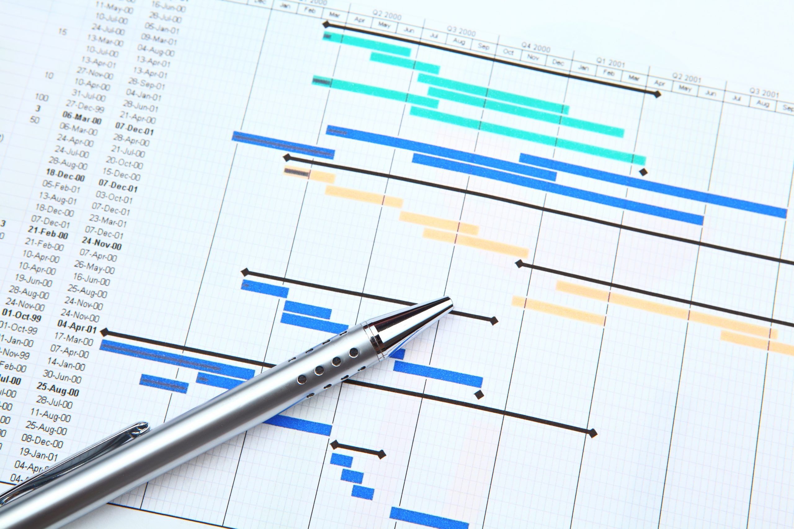
InStandart development process

How We Work

  • Sprint-based delivery – 2-week cycles, demo at the end of each. You see progress, not status reports.
  • Direct access to engineers – No account managers relaying messages. Your team talks to the people building the solution.
  • Adapts to complexity – A formwork calculation tool and a multi-discipline 3D review platform require different processes. We scale the methodology to your project, not force it into a template.


Same process for non-CAD software projects. The methodology adapts – sprint cycles, working prototype, direct engineer access – for SaaS platforms, enterprise integrations, and mobile/web apps when those align with our engineering focus.
Case Studies

Real projects, real results

POSforAFS: Automating Formwork Calculations Directly Inside AutoCAD

Built on FormCalc, configured to the client’s proprietary panel system and rules.

Formwork calculation ran days to weeks per project, and any design change meant redoing much of it from scratch. Two engineers on the same structure arrived at different panel counts, so quality control was guesswork – and an experienced engineer being unavailable stalled the job.

Result: 70% lower calculation cost. 85% faster turnaround – weeks to hours. Panel reuse optimised systematically instead of by judgement, and senior engineers freed for design work.

Read More About POSforAFS
POSforAFS: Automating Formwork Calculations Directly Inside AutoCAD

FormCalc for TEBAU: Wall & Slab-Edge Formwork Automation

Dividing every wall into panel sections with the most reuse across pours is a combinatorial problem – done by hand, 30-90 minutes per layout, redone on every drawing change. Slab-edge formwork had no tool at all.

We built a FormCalc-based AutoCAD plugin that lays out the panels, resolves corners, tracks reuse across pours, and generates the bill of materials – plus a module for the slab edges nobody had automated.

Result: layout from 30-90 minutes to ~2 minutes, bill of materials automatic and always in sync with the model.

View More
FormCalc for TEBAU: Wall & Slab-Edge Formwork Automation

Operator Training Simulator for an Air Separation Unit Built from Detailed Design

Traditional training took 4-6 months with safety incidents during hands-on practice. Emergency scenarios couldn’t be practiced on live equipment – too dangerous. New operators felt unprepared when emergencies actually occurred. We built a Unity-based 3D training simulator from their P&IDs and process models. Operators practice normal operations, startup/shutdown procedures, and emergency responses in a safe virtual environment – making mistakes and learning without real-world consequences.

Onboarding from 4-6 months to 2-3 months, training cost per operator down 60%, procedure retention from around 60% to over 90%, incidents during onboarding down 80%, emergency response preparedness up 70%.

See More Details
Operator Training Simulator for an Air Separation Unit Built from Detailed Design

Dwg2ExcelExporter: Automated Data Extraction from AutoCAD Drawings to Structured Excel Reports

Dimensions, quantities and material codes sit locked in drawing geometry. Getting them into a spreadsheet meant reading values off the screen and retyping them – hours per drawing set, with every misread digit propagating into procurement and cost estimates before anyone noticed.

We built an AutoCAD plugin that scans the drawing, extracts against configurable criteria, runs the calculations, and generates a formatted Excel report.

Result: reporting from hours to seconds. Transcription errors eliminated. Every report reflects the current drawing revision.

See Full Case
Dwg2ExcelExporter: Automated Data Extraction from AutoCAD Drawings to Structured Excel Reports

3D Model Review Tool for Multi-Disciplinary Clash Management on a Gas Processing Facility

Four disciplines coordinating a gas processing facility, with clashes tracked in spreadsheets and model revisions circulating without version control. Resolving a single clash took three to five days, most of it spent establishing who owned it.

We built a platform with a smart clash register, named ownership, version control, and live dashboards.

Result: clash resolution from 3-5 days to under 1 day. Duplicate clashes down 90%.

View More Details
3D Model Review Tool for Multi-Disciplinary Clash Management on a Gas Processing Facility

Keraglass: Automating Glass Embossing Drawing Preparation Inside AutoCAD

Every embossing order meant placing circle patterns along the glass contour by hand – diameters, spacing, row counts, element by element. Hours of drafting per drawing, restarted for every new size, and a single missed fill meant rerunning the job.

We built an AutoCAD plugin that generates the full pattern from a few inputs, fills closed areas in one command, and stores the parameters inside the drawing for reuse.

Result: drawing preparation from hours to minutes. Fill errors eliminated. Consistent output regardless of who runs it.

Know More
Keraglass: Automating Glass Embossing Drawing Preparation Inside AutoCAD

Integration of CAD/BIM with SAP for a Midstream Gas Processing Plant

Engineering worked in Plant 3D while procurement ran on SAP, with no automated connection between them. Every Engineering BoM – thousands of line items per package – was re-entered by hand at roughly 4 hours and a ~15% error rate. Project managers had no view of material availability during design, and asset handover to operations ran consistently 6+ weeks late.

BoM entry ~4 hours → under 15 minutes per package. Errors ~15% → under 2%. Handover 6+ weeks → 1 week. Asset registration ~10 days → same day. Roughly $120,000 in annual engineering labour savings – about 1,200 hours at a $100/hour rate.

More Information About Case
Integration of CAD/BIM with SAP for a Midstream Gas Processing Plant
Starting a project with InStandart

Why Work With Us?

  • Engineering-First Team – We speak the language of formwork systems, pipe routing, and structural calculations – not just code. Your project leads are CAD engineers, not project managers relaying requirements.
  • Proof Before Commitment – Every project starts with a working proof-of-concept on your real data. You validate the approach before full build – no wasted budget on assumptions.
  • Measurable ROI – Our clients see concrete results: 70% cost reduction in formwork calculations (POSforAFS), 80% fewer manual errors in clash management, error rates below 2% in CAD-to-SAP sync.
  • Fixed-Price After Audit – No time-and-materials surprises. After the engineering audit, we deliver a fixed-price proposal tied to specific deliverables. You know the budget before you commit.

Describe your engineering challenge. We'll outline the process and timeline in a 30-minute call.

38 Middlehill Road,
Wimborne, BH21 2SE