

The Role of CAD in Engineering and Product Design
In the world of product engineering and design, innovation is constant. Computer-aided design (CAD) has become the cornerstone of this evolution. It bridges the gap between id...
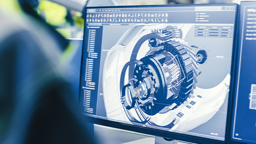
In the world of product engineering and design, innovation is constant. Computer-aided design (CAD) has become the cornerstone of this evolution. It bridges the gap between ideas and reality, giving professionals the ability to create, test, and refine designs with astonishing accuracy.
CAD platforms – AutoCAD, Revit, AVEVA E3D, SolidWorks – provide the foundation. But in construction, oil and gas, and manufacturing, the real productivity gains increasingly come from what engineering teams build on top of these platforms: custom plugins for automated calculations, CAD-to-ERP data synchronization, interdisciplinary clash detection, and training simulators built from design models.
This article covers both halves – what the platform does, and where the custom layer begins.
Role of CAD in Engineering
CAD is not just a tool; it is a game changer. Engineers rely on CAD software to develop complex designs that were once impossible or time-consuming. The software can create detailed 2D drawings and complex 3D models, giving professionals the ability to visualise and analyse their designs in depth.
For example, in mechanical engineering, CAD allows for the design of complex machines. Designers can virtually test components, reducing the need for physical prototypes. This saves time and resources. What’s more, CAD easily integrates with simulation tools, allowing for stress testing and performance analysis before actual production begins.
In practice, the bottleneck in engineering CAD workflows isn’t the design itself – it’s what happens after design. Data transfer between CAD and enterprise systems, BoM compilation, cross-discipline coordination, and report generation consume disproportionate engineering hours. A midstream gas processing plant project found that BoM data entry alone took 4 hours per update with 15% error rates – not because AutoCAD Plant 3D couldn’t generate the data, but because there was no automated path from CAD to SAP. A custom integration plugin compressed this to 15 minutes with errors below 2%.
CAD in Product Design: Fostering Creativity and Precision
In product design, creativity meets practicality. CAD supports both. Designers can translate their ideas into tangible concepts faster and more accurately. The software makes it easy to experiment with shapes, sizes, and materials. With CAD, customising a design is effortless, allowing for multiple iterations in a short time.
In addition, CAD ensures consistency in product design. By using templates and libraries of standard components, designers maintain consistency. For industries such as automotive or consumer electronics, this consistency is critical. It meets branding and functionality requirements.
For specialised manufacturing – like glass embossing or formwork for concrete construction – CAD’s standard capabilities cover basic modelling, but the domain-specific logic that makes designs production-ready requires custom automation. One construction firm automated formwork panel selection and optimisation directly inside AutoCAD, reducing formwork calculation costs by 70% and turnaround by 85%. The CAD platform provided the geometric foundation; the custom algorithm provided the engineering intelligence.
Advantages of Using CAD
Increased accuracy. CAD reduces human error. It offers tools for precise measurements and accurate alignment, ensuring that designs meet strict specifications.
Cost-effective. By minimising the need for physical prototypes, CAD reduces costs. Virtual testing also prevents costly errors during the manufacturing process.
Collaboration. Modern CAD software allows teams to collaborate in real time. Designers, engineers, and clients can access the same files, make suggestions, and make changes instantly. In multi-discipline projects – where piping, structural, electrical, and instrumentation teams work on the same facility – collaboration means more than shared files. It requires interdisciplinary clash detection with version control, so that a resolved clash in one discipline is automatically reflected across all views.
Integration with manufacturing. CAD files integrate directly with computer-aided manufacturing (CAM) systems, streamlining production from CNC machining to 3D printing.
Where Standard CAD Ends and the Custom Layer Begins
Standard CAD platforms handle geometry, modelling, simulation, and basic collaboration well. What they don’t handle is everything that happens at the boundary between CAD and the rest of the engineering business – and that’s where the compounding cost sits, because those workflows repeat on every project, every day.
| Workflow | Standard CAD platform | What the custom layer adds | Documented result |
| Design geometry and documentation | Covered | – | – |
| Domain-specific calculations – formwork, take-offs, load checks | Not covered | An optimisation algorithm reading structure geometry directly from the drawing | Calculation cost −70% · turnaround +85% · weeks → hours |
| CAD ↔ ERP data flow | Not covered | Bi-directional sync with rules-based mapping and a validation pipeline | BoM entry 4 h → 15 min, errors 15% → under 2%, data sync +85%, reworks -70% |
| Cross-discipline clash management | Detection only | Resolution tracking with named ownership, deadlines, and model version control | clash resolution 3-5 days → under 1 day · duplicate clashes -90% · review cycle ~10 days → 3-4 days |
| Drawing data → structured reports | Raw export only | Extraction, transformation, calculation, and formatting in one pipeline | Reporting hours → minutes, formatting errors eliminated |
| Handover to operations and training | Not covered | A simulator built from the facility’s own design model and P&IDs | Training time 4-6 months → 2-3 months, onboarding incidents -80%, cost per operator -60% |
Every row above is a workflow that a standard platform performs adequately for its own purpose and not at all for the one downstream of it. The platform was necessary in each case; it was never sufficient.
Getting the sequence right
Knowing where the custom layer belongs is the easy half. The harder question is which workflow to automate first, and the answer is rarely the technically interesting one – teams routinely build a title-block generator while their engineers spend four hours a day re-keying Bills of Materials. The failure modes are consistent enough to list, and we’ve done that in 5 CAD Automation Mistakes That Waste Engineering Budgets.
As for what’s genuinely changing in the platforms themselves – ML-based geometry generation, frameworks for training models on CAD data – the useful distinction is between the capabilities that need a model and the ones a deterministic rule handles better and cheaper. That’s covered in Machine Learning in CAD.
Conclusion
CAD has transformed engineering and product design – that’s established. The open question for engineering teams isn’t whether to use CAD, but how much of the platform’s potential they’re actually capturing.
If your team uses AutoCAD, Revit, AVEVA E3D, or SolidWorks and still spends significant hours on manual data transfer, report formatting, calculation workflows, or cross-discipline coordination – that’s the gap where custom CAD automation delivers measurable results.
Share this post:
Which row in that table describes your team?
Tell us which of those workflows costs you the most engineering time and which platform it runs on. We'll give you an honest read on what closing that gap would take – including when the answer is that your standard platform already covers it.