

Computer-Aided Design (CAD): Transforming Reality
Computer-Aided Design (CAD) is the foundation of modern engineering. Every building, pipeline, industrial plant, manufactured product, and piece of infrastructure is designed ...
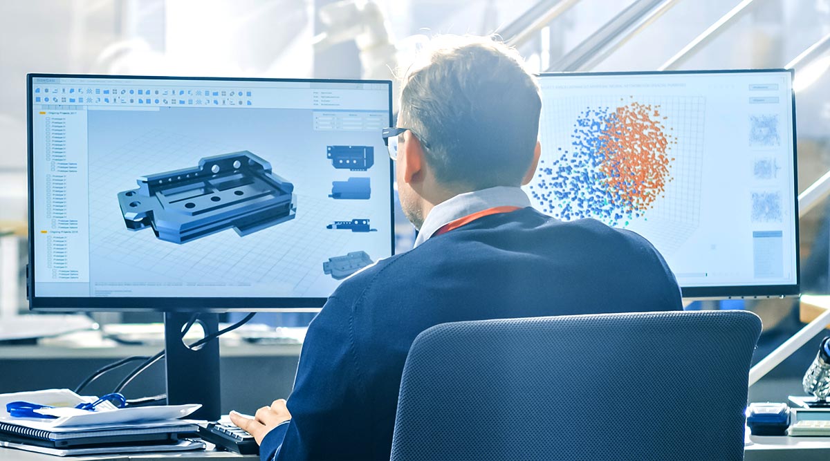
Computer-Aided Design (CAD) is the foundation of modern engineering. Every building, pipeline, industrial plant, manufactured product, and piece of infrastructure is designed in CAD before it exists in the physical world. AutoCAD, Revit, AVEVA E3D, SolidWorks, and Intergraph Smart 3D are the platforms that engineering teams depend on daily.
But the role of CAD has expanded well beyond design. CAD data now feeds digital twins, drives automated procurement through ERP integration, powers training simulators, and enables real-time interdisciplinary coordination. The platforms themselves haven’t changed fundamentally – what’s changed is what teams build on top of them.
This article covers what CAD is, how it works, where it’s used across industries, and where it’s headed – including the shift toward custom automation, AI integration, and enterprise connectivity that defines CAD engineering today.
What is Computer-Aided Design (CAD)?
Computer-Aided Design, or CAD, refers to the use of computer technology to aid in the creation, modification, analysis, or optimisation of designs. Unlike traditional drafting methods that relied on manual drawings and physical prototypes, CAD enables designers and engineers to create precise, digital representations of their ideas. These digital models serve as a virtual blueprint, allowing for efficient visualisation, analysis, and modification of designs before they are brought into the physical realm.
In practical terms, CAD means different things in different industries. For an oil and gas engineering team, CAD is AutoCAD Plant 3D or AVEVA E3D – used for 3D piping models, P&IDs, and equipment layout. For a construction firm, it’s AutoCAD or Revit – used for structural design, formwork planning, and BIM coordination. For a manufacturer, it’s SolidWorks or Inventor – used for product modelling and simulation.
The CAD platform defines the starting point. What engineering teams build on top of it – custom plugins, ERP integrations, automated calculations, clash detection tools – determines whether CAD delivers its full potential or leaves productivity on the table.
Origins and Evolution of Computer-Aided Design
The roots of CAD can be traced back to the early 1960s when computer technology was in its infancy. The first CAD systems were primarily used for aerospace and automotive design, aiming to streamline the design and manufacturing processes. As technology advanced, CAD systems evolved from simple 2D drafting tools to sophisticated 3D modelling environments.
The 1980s marked a significant milestone with the development of commercial CAD software. Companies like Autodesk emerged, introducing accessible and user-friendly CAD solutions to a broader audience. This democratisation of CAD technology paved the way for its widespread adoption across diverse industries.
By the 2020s, the next major shift was underway: CAD platforms becoming programmable foundations rather than standalone tools. Autodesk, AVEVA, and Siemens opened their APIs for deep customisation. Engineering teams began building custom plugins in .NET and Python that automated domain-specific tasks – from formwork calculations to CAD-to-SAP data synchronisation – directly inside the CAD environment.
The trajectory is clear: CAD is evolving from a design tool into a programmable engineering platform.
Key Components of Computer-Aided Design
- Geometric modelling. CAD systems enable the creation of digital models by defining shapes and dimensions in a virtual environment. Geometric modelling serves as the foundation for all design work, allowing users to build and manipulate objects with precision.
- Rendering and visualisation. CAD software provides realistic rendering, allowing designers to visualise their creations in lifelike detail. This aids communication and decision-making by offering a clear representation of the final product. What the model has to be accurate about differs by purpose – a model detailed enough to render well may be useless for generating a Bill of Materials, and the two requirements are not the same.
- Parametric design. Changes to one aspect of a design automatically update related elements, ensuring consistency and reducing the likelihood of errors. Encoding a repetitive, geometry-driven task as a set of rules is where parametric work stops being a convenience and starts showing up in the project budget.
- Simulation and analysis. CAD tools facilitate the simulation and analysis of designs, enabling engineers to assess structural integrity, thermal performance, and fluid dynamics. This helps identify potential issues early, minimising costly revisions.
- Integration and automation. Modern CAD workflows extend beyond the design environment. CAD data flows into enterprise systems (SAP, Oracle ERP, Teamcenter), simulation tools (CAESAR II, Aspen HYSYS), and operational platforms (SCADA, BMS). Custom integration layers built with native CAD APIs automate data transfer, validation, and reporting that would otherwise require hours of manual processing. This is often where the largest practical ROI lies: automating the data flow between CAD and enterprise systems consistently delivers greater time savings than automating the design process itself.
Where Computer-Aided Design Is Used
CAD is indispensable across industries – but what separates teams isn’t the platform they run. It’s what they’ve built on top of it.
| Industry | Typical platform | What teams build on top | Documented result |
| Construction & BIM | AutoCAD, Revit | Automated formwork calculation driven directly from drawing geometry | Formwork cost -70%, turnaround +85% |
| Oil & gas, EPC | AutoCAD Plant 3D, AVEVA E3D | BoM synchronization with SAP, interdisciplinary clash detection, automated data extraction | Data sync +85%, data-related reworks -70% |
| Industrial operations | Detailed 3D model plus P&IDs | Operator training simulators built from the design model rather than a generic library | Training time 4-6 months → 2-3 months, onboarding incidents -80% |
| Manufacturing & fabrication | SolidWorks, Inventor, AutoCAD | Drawing preparation automation, structured data extraction into reports and CAM workflows | Drawing prep and reporting from hours to minutes |
Beyond production, CAD also underpins computer-aided manufacturing, where digital designs become instructions for CNC machining and other automated processes. In every row above, the platform was necessary and not sufficient – the measured result came from the layer built on top.
Challenges in CAD Adoption and Customisation
The primary challenge today is not CAD itself – the platforms are mature and capable. The challenge is what happens between CAD and the rest of the engineering ecosystem.
Data interoperability remains the biggest practical bottleneck. Engineering teams work across AutoCAD, Revit, AVEVA E3D, CAESAR II, Aspen HYSYS, and SAP – systems with different data models, file formats, and APIs. Manual data transfer between them introduces error rates of 10-15% and consumes thousands of engineering hours annually.
Domain-specific limitations are the second challenge. Standard CAD platforms don’t include algorithms for formwork optimisation, oil and gas material coding, or jurisdiction-specific compliance checking. These require custom development using native CAD APIs – a skillset that combines software engineering with deep domain knowledge, and one that is notoriously hard to hire.
What’s Changing Now
Several concrete developments are reshaping the CAD landscape. Autodesk’s Neural CAD introduces machine-learning-based geometry generation in Fusion and Forma. Tech Soft 3D’s HOOPS AI provides the first purpose-built framework for ML workflows with CAD data. PTC Creo 12 integrates AI-driven generative design with thermal physics simulation.
The pattern behind these announcements matters more than any individual product: ML capabilities are becoming native to CAD platforms. That means access to them stops being a differentiator – everyone will have them. What separates teams is how effectively those capabilities connect to enterprise systems, simulation environments, and operational processes.
For most engineering teams, the highest-impact change is more practical than any of the above: the ability to extend CAD platforms with custom automation. Automated BoM compilation, CAD-to-ERP data sync, interdisciplinary clash management, compliance checking, and training simulators built from existing 3D models are the capabilities that deliver measurable ROI today, not in a future product roadmap. Which of those genuinely need a model, and which need deterministic rules, is a question worth answering before you commission anything.
Conclusion
CAD is the foundation. What you build on top of it determines whether your engineering team operates at capacity or loses hours to manual processes, data re-entry, and workarounds.
The scale is easy to underestimate. On one midstream gas processing project, manual BoM re-entry alone consumed roughly 1,200 engineering hours a year – about $120,000 at a $100/hour engineering rate, from a single workflow, before counting the procurement errors it caused downstream.
Share this post:
Using AutoCAD, Revit, AVEVA E3D, or SolidWorks and wondering what's worth automating?
Tell us which workflow consumes the most engineering time in your team and which platform it runs on. We'll give you an honest read on what automating it would cost and return – including when the answer is that your current setup is already fine.