FormCalc for TEBAU: Wall & Slab-Edge Formwork Automation
«We weren’t sure everything they promised was even possible. In the end, they delivered exactly what was promised. A real pleasure to work with.» – Ladislav Zahradník, L...
«We weren’t sure everything they promised was even possible. In the end, they delivered exactly what was promised. A real pleasure to work with.» – Ladislav Zahradník, Lead Engineer, TEBAU
TEBAU – a Slovakia-based concrete formwork supplier – runs its design work in AutoCAD. But two of the hardest tasks in formwork engineering weren’t automated by the software they used, and stayed manual: wall panel optimisation, and slab-edge formwork – the latter with no tool support at all, since no manufacturer even publishes guidelines for it.
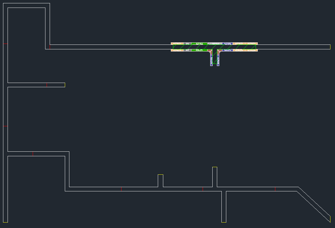
InStandart closed both. Implemented on FormCalc and configured to the client’s panel catalogue, the solution runs as a production AutoCAD plugin that turns a drawn wall channel into a fully detailed, catalogue-accurate formwork model – and generates the bill of materials automatically.
Project Summary
| Industry: | Concrete formwork supply & temporary works engineering |
| Business Goal: | Automate wall panel layout, corner detailing and slab-edge formwork to cut engineering time and material waste |
| Integration: | Autodesk AutoCAD 2023 (.NET API – reads existing DWG drawings as input) |
| Panel systems: | Manufacturer standard catalogue |
| Core Technologies: | C#, .NET Framework 4.7.2, AutoCAD 2023 .NET API, WPF, custom Ribbon |
| Status: | In production – running on live projects |
The Problem: Software Stopped at the Two Hardest Parts
Formwork defines the temporary mould into which concrete is poured and held until it sets. Getting the panel arrangement right – across multiple pour stages, corners, openings and reuse cycles – is skilled, unforgiving engineering work. The software TEBAU worked with handled the routine parts but stopped precisely where the difficulty is:
- Wall optimisation was left to the engineer. Walls have to be divided into sections that are as equal as possible so the unused material between sections is minimised. That is a combinatorial problem none of the tools they used solved – so it was done by hand, wall by wall, floor by floor.
- Slab-edge formwork had no automation at all. No formwork manufacturer publishes guidelines for it, so no tool existed – it was purely manual work, every time.
- Time scaled with geometry. One to two hours per floor on simple structures, up to twelve on complex ones – then multiplied across floors and across every parallel project.
- Reuse across pour stages is where cost is won or lost – and it is the hardest thing to optimise by hand. Balancing panel reuse across a pour series involves too many variables to reliably land on the most efficient configuration manually, which pushes panel counts and material cost up.
- Every drawing change meant redoing sections. Any revision to the geometry forced the engineer back into affected zones from scratch.
The Solution: FormCalc, Configured to the Client’s Panel System
Rather than replacing the engineer’s workflow, the plug-in fits inside it – engineers work in AutoCAD as they always have, and the tool handles the detailing and calculation layer. At its core is a geometry-driven layout engine that turns wall geometry into a fully detailed formwork model. It selects and arranges the client’s existing catalogue panels – a combinatorial optimisation, not geometry generation.
- Automatic panel layout along the channel walls. Overlap zones between the two parallel faces are detected, and panel combinations are chosen by width and height against the manufacturer standard catalogue, honouring fit tolerances and permitted overhangs.
- Multi-tier height selection (a primary tier plus an additional band) is driven by per-height rules covering walls from 900 mm to 5400 mm.
- Corner and narrow-channel handling. Inner and outer corners (90° / 270°), hinged corners, corner elements and corner-adjustment fillers are resolved automatically, with dedicated rules for narrow 250 mm channels and typical corner gaps.
- Reuse-aware optimisation across a pour series. A single shared stock is tracked across successive pours, and selection plus post-optimisation passes work against the real remaining quantities – not theoretical ones. Both parallel faces of a wall stay identical (mirror symmetry), and reuse swaps act on both walls atomically, even under limited stock.
- Persistent model and automated outputs. The formwork model is serialised into the drawing (NOD JSON + XData), so it survives closing the DWG. Plan, contour and side-view representations are generated automatically, and the bill of materials exported by section – always in sync with the model. Editing commands move cut-lines, draw side views, or delete a specific panel by a stable id without breaking the model.
- Slab-edge module. The same toolset includes a dedicated slab-edge module – the second gap the manufacturer software never addressed – bringing the previously all-manual edge formwork into the same automated flow.

Results
Measured against the client’s manual formwork workflow before the plug-in was deployed.
Confirmed today:
- The bill of materials is generated automatically and kept in sync with the model – no manual recount.
- The solution is in production.
| Metric | Manual | FormCalc deployed |
| Time to produce a panel layout | 30–90 minutes | ~2 minutes – up to ~45× faster (reported by the client’s lead engineer) |
| Bill of materials | Manual recount, error-prone | Automatic, instantly generated |
“We’d been looking for this for 20 years – nobody could adapt to our system.”
Why This Is Hard (and Why Generic Tools and AI Code Generation Don’t Solve It)
Formwork optimisation looks like a solved problem until you try to automate it against real drawings and a real panel catalogue. Four reasons this required purpose-built engineering, not a generic tool or an AI-generated script:
- Reuse optimisation is combinatorial. The number of valid panel configurations grows exponentially with structure complexity, and the reuse dimension couples every pour to the ones before it. Manual work lands on pragmatic-but-suboptimal answers; a generic tool or a one-shot generated script can’t hold the constraint set. A purpose-built algorithm working against the real remaining stock can.
- Mirror-wall symmetry under limited stock. The two faces of a channel must stay identical – joints, corner fillers and reuse swaps coordinated so both walls match, and applied atomically. That is tight, stateful coordination, not a scriptable pass.
- Robustness to drawing imprecision. Real DWGs carry coordinate noise. Tolerances and projection maths absorb it so real-world drawings resolve cleanly instead of throwing edge-case failures.
- Corner geometry with no shortcut. Narrow channels and mixed 90° / 270° corners need special clips and adjustment stacks that mirror the neighbouring panel column height – rules encoded from formwork engineering, not from a catalogue lookup. And slab-edge had no prior art at all: with no manufacturer guidelines to lean on, the logic was built from the engineering up.
Where This Approach Works
The same AutoCAD-integrated approach applies wherever formwork engineering is geometry-driven, repetitive, and currently done by hand in parallel with a CAD workflow:
- Formwork suppliers and rental companies that provide engineering design alongside panel systems (DOKA, PERI, MEVA, Hünnebeck and similar catalogues) – where faster, more accurate layout is a direct competitive advantage.
- Temporary works consultancies designing falsework and formwork for main contractors, currently running high volumes of calculations through spreadsheets and manual layout.
- High-volume residential and complex commercial / civil concrete work, where the same layout workflow repeats across many floors and projects and automation compounds.
In every case the tool complements the software teams already use rather than replacing it – it automates the tasks still left to manual work, inside the AutoCAD environment engineers already know.
Related:
Share this post:
Frequently Asked Questions
What is slab-edge formwork automation?
Slab-edge formwork is the temporary edge form that holds concrete at the perimeter of a floor slab, and automating it means generating that perimeter formwork – layout and components – straight from the drawing instead of detailing it by hand. It has historically been all-manual: formwork manufacturers publish no guidelines for it, so no off-the-shelf tool existed. This plug-in brings slab-edge detailing into the same automated AutoCAD flow as wall panels.
Does this replace our formwork manufacturer’s software?
No – it complements it. Engineers keep working in AutoCAD with the tools they already have; the plugin only automates the tasks left to manual work – wall panel optimisation and slab-edge formwork. It is an added layer inside the existing workflow, not a replacement.
Which AutoCAD versions are supported?
The plugin is built on the AutoCAD 2023 .NET API and runs in production on AutoCAD 2023. Because it integrates at the .NET API level, support for other AutoCAD releases is scoped per deployment.
How is this different from the panel layout our manufacturer’s tool already produces?
Manufacturer tools place panels but leave the optimisation to the engineer – how to divide a wall into sections with the least wasted material, and how to reuse panels across pour stages. That is a combinatorial problem normally solved by hand. This plug-in solves it automatically, works against your real remaining panel stock, and keeps both faces of a wall consistent.
Can it work with our panel system (DOKA, PERI, MEVA, Hünnebeck)?
Yes – it is configured to your catalogue. The optimisation works with your actual standard panels, corner elements and fillers, so the output is directly usable for procurement rather than theoretical.
Does it generate new panel geometry, or use our existing panels?
It uses your existing catalogue panels. The engine selects and arranges standard panels from your system – a combinatorial optimisation – rather than generating new geometry, which is what keeps the output buildable and procurement-ready.
How much engineering time does it actually save?
On this deployment, producing a panel layout dropped from 30-90 minutes of manual work to about two minutes. The bill of materials is generated automatically and kept in sync with the model, removing the manual recount step entirely.
Testimonial from the client
It was a real pleasure working with them
Firstly we were cautious about InStandart. We never heard about such company, nor we didn’t know if something like things that were promised, were possible. In the end InStandart proved itself. They were always consulting direction of the project. They made corrections, if something was wrong and incorporated every demand. Every two weeks they delivered a new version and by the end of the project it was even every week. And mainly they delivered what was promised. It was a real pleasure working with them.